10+ motor block diagram
Block Diagram and Transfer Function of DC Motor Armature Controlled DC Motor. Intel Stratix 10 Block Diagram 15.
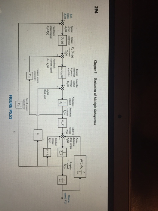
Solved 79 Hybrid Vehicle Figure P5 53 Shows The Block Chegg Com
Simple Servo System Block Diagram Figure 2-3 view A is a block diagram of a closed-loop position servo.

. The engine block is a structure that contains the cylinders and other components of the internal combustion engine. 2002 Instrument panel The fuse block is in the instrument panel on the drivers side. Note the Greek letter Sigma meaning summation AKA the Controller.
J is the moment of inertia 001 kgm 2 damping ratio is denoted by b 01 Nms the electromotive force constant is represented by K. An example of a wiring diagram for a motor controller is shown in Figure 1. Generally stepper motors are operated by electronic circuits mostly on a dc power supply.
Choose a template Pick a block diagram template that best matches the system. Launch Canva Open Canva on your desktop browser or mobile app and search for block diagram. In DC motor following parameters 6 are considered.
Engine diagram drawing exploded motorcycle. Innovations in Intel Stratix 10 FPGAs and SoCs 13. Note that symbols are discussed in detail later.
Working of Stepper Motor. Intel Stratix 10 FPGA and SoC Family Plan 16. The engine dataplate provides model identification as well as other important information about the engine.
Chevrolet S-10 2002 fuse box diagram Year of production. Dashed lines indicate a. FPGA and SoC Features Summary 14.
Consider the armature controlled dc motor and assume that the demagnetizing effect of armature reaction. Motor controller example. The design of the cylinder block depends on the features and type of the.
The Chevrolet small block 350 engine is a 60 liter overhead valve V-8 engine that is built for the small Chevy truck models. Power plant diesel layout engine diagram line single solar engineering mechanical electrical google eee community sg. The engine dataplate is located on the fuel pump side of the rocker housing.
Stepper motor working principle. The 350 engine was made from 1970 until 1990. The block diagrams are drawn for a few basic synchronous motor structures ie an SPM motor a salient-pole permanent magnet motor and a synchronous reluctance motor.
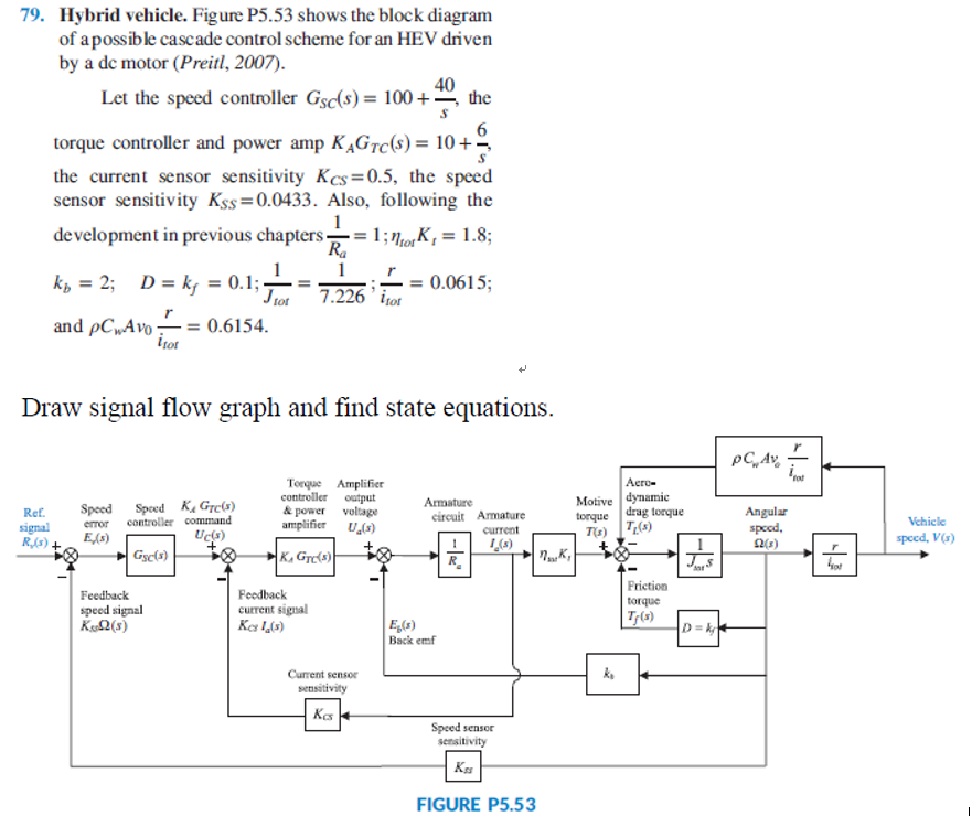
Solved 79 Hybrid Vehicle Figure P5 53 Shows The Block Chegg Com
All About Shunt Dc Motors What They Are And How They Work

10 Practical Examples Of Open Loop Control System Etechnog

Motor Drives Application Examples Semikron

Ford Focus Engine Diagram Xl Ford Focus Engine Ford Focus Engineering

Solved 1 P5 79 Hybrid Vehicle Figure P5 53 Shows The Chegg Com

Tecumseh Magneto Wiring Diagram Tecumseh Diagram Electrical Diagram
2

10 1994 Ford F150 Engine Wiring Diagram 1994 Ford F150 F150 1995 Ford F150

10 1977 Trans Am Engine Wiring Diagram Trans Am 1979 Pontiac Trans Am 1977 Trans Am

10 Nissan Micra K12 Engine Wiring Diagram
All About Dc Motor Controllers What They Are And How They Work

10 General Electric Furnace Wiring Diagram Electrical Diagram Electric Furnace Washing Machine Motor

10 Kubota Zg23 Engine Wiring Diagram Trailer Light Wiring Electrical Diagram Electrical Wiring Diagram
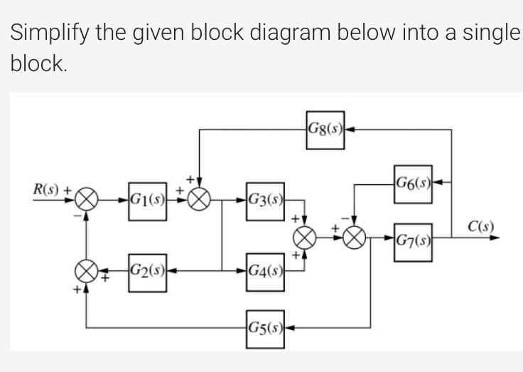
Answered Implify The Given Block Diagram Below Bartleby
Coleman 1468a 3029 Oem Motor Replaces Fasco 7128 0392 1468a 3029 Emotorpro
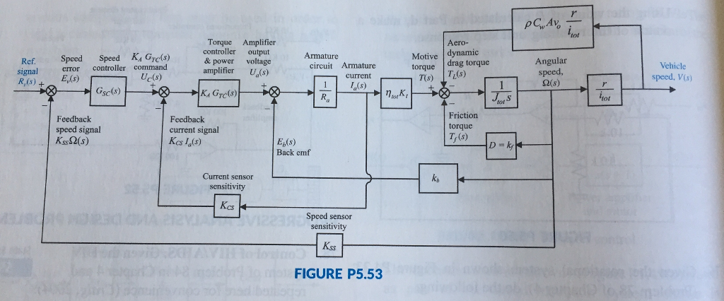
Solved 79 Hybrid Vehicle Figure P5 53 Shows The Block Chegg Com